In a robust hardwood case. Both front and back have a hinged lid with chains. There are
grips on the left and right hand side of the case. At the top of
the receiver a row of binding posts for antenna,
+30 volts, 0, +4 volts, and earth.
On the upper side of the ebonite front there are binding posts
that make it possible to connect an extra hf pre-amplifier or an
lf amplifier. The radio is operated by a number of controls,
situated at the front. Sliding resistors for filament and anode
voltages are situated at the extreme left and right. In the
middle the detector: a Philips
C1 gas filled bright emitter. The tube is almost identical to
the Philips Ideezet tube, issued in 1918. Behind this tube a
four pin connection for a Philips D1 (a later addition?) is
visible (see photo below). For tuning two variable condensers
are available. Both can be operated by two Bakelite knobs with a
scale (0..100). The left one is used to tune the primary (antenna)
circuit; the second one is used to tune the secondary circuit. Both
circuits form a so called "band-pass filter". This construction
offers better selectivity compared to a single circuit. Above
the detector a threefold coil base is visible. Coil functions
from left to right: primary coil, secondary coil, reaction coil.
All coils are plug in types.
A set of 11 coils is available. The coils measure
20,5 mm between the pins, a distance that deviates from Dutch
standards. A handle with a remarkable long shaft and an extra
bearing can be used to change the position the coils on the left
and right. The coil on the left adjusts the coupling factor of
the band-pass filter, the right coil adjusts the amount of
reaction. Band width and selectivity both depend on this. With the coils available the
receiver has a receiving range of 250 to 6000 meters.
Between the coils
and the sliding resistors two further knobs can be seen. The
left one is used to switch the antenna circuit
(serial/parallel). On the right a bipolar on/off switch that
operates the filament voltage and the anode battery. Below the
tuning knobs two short-circuit bridges to
protect the variable condensers, as well as two sets of terminal
sockets for a headset. The fixed condensers
are by Dubilier Ltd. All materials, like the terminal sockets,
clamps for the detector tube, the coil set, seem to be British
(Marconi) and some also appear in the product catalogues of the
Dutch NSF factory. The construction of the set suggests professional
use. The radio could have been used near a transmitter.
Receivers like this were used in shipping and in the army. It
could also have been used as an experimental receiver for the
Dutch (or Dutch East Indies) PTT.
The
circuit of the receiver is almost identical to this
circuit, published by J. Corver in 1920.
Listen to "We gaan
naar Zandvoort" sung by Albert Bol with orchestra,
recorded in 1920
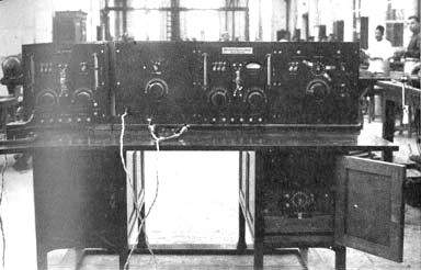
The receiver looks a bit like the long wave
receiver shown in the picture opposite (the unit on the
left of the table).
The receiver hasthe same
frontstructure witha centrally mountedvalve andtwolarge sliding
resistors,left and right onthe front.
The coilswere possibly placedinsidethis
unit.
Dr.Ir.C. J.deGrootordered
the construction ofthis unitin the Dutch EastIndies inthe
mainworkshop of theP.T.TService
inWeltevreden.It was shipped to the Netherlands inthesecondhalf of the year1918 with the
warshipHMS"De Zeven Provinciën".
It arrivedinFebruary 1919. During
the journey, receptiontests were
carried out.
This unitreceivedthefirstsignals
fromthe100kWtransmitter
Malabarin the Dutch EastIndiesto the
Netherlands onJune 5, 1919at de Meent
in Blaricum.
The unit
arrived inthe Netherlands inthe receiving station
ontheMeentin Blaricum. In the
picture,left,
MrP.C.Tolk,right,presumablyMr Visser.
Detail
Philips 4 volt / 0,5 A low vacuum tube,
Va 25-30 volts, presumably a C1,
filled with Argon. "8178" is printed on the upper
socket, "P"
(plate) on the lower socket. The name "Philips" is etched in the glass
tube; the glass support structure inside shows the date code
24/3 in ink.
Interior
Visible are two
variable condensers with zinc plates. In the middle two
Dubilier condensers. On the right a support for the
earpiece of a headset.
Top, with a number of binding posts
The closed cabinet
The complete set of inductance coils
Philips
receiver tube type C. From a Philips folder, October 1921


.jpg)


.jpg)
.jpg)
.jpg)
.jpg)
.jpg)