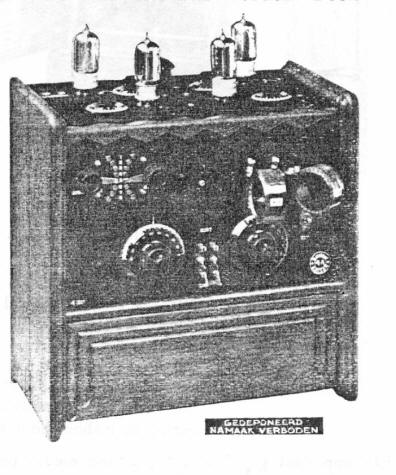
Because the receiver was made between
1926 and 1928, it underwent some changes. The first
model had lamps on the top and coils at the front, in a
later model (picture left) the tubes are fitted internally
and the coils are still at the front. Photo 2 shows a
slightly larger 1927 model, with internal tubes and
internal feedback. The third device has a flap on the
front and top. Strength control is somewhat simplified,
the knobs are symmetrically distributed over the front
and the tumbler switch in this model is now a push/pull
switch. All radioss work with resistance amplification.
The tube layout is unknown but probably will have looked
like this: HF: A409, detector: A409/A415, LF1: A425, LF2: B406. The receivers from 1927 and 1928
have an extra antenna socket and a connection for
headphones. The long wave with these radios is divided
into 2 parts: 800-2300 and 2300-3200 meters. The medium
wave range is 200-800 meters.
The
radios are not only beautiful to look at, the chassis
are also very well designed.
The radio was
advertised in leaflets and advertisements as: "built in The
Netherlands by Delft engineers".It was most
likely made by Radio-Technisch Bureau
"Broadcast", Sonoystraat 75 in The Hague.
The owner of this company was H.G.A.
Rundervoort.
In any case, Delft
engineer L.H.M.
Huydts (also working at Waldorp) contributed to
the receiver: he designed "strength control". The antenna
coil in the Koomans circuit is tapped into 8
taps for course tuning to the wavelength. A
variable capacitor is connected in parallel to
this coil, which uses the same taps. These taps
are also used to couple the detector grid to a
smaller or larger part to the coil. The
advantage of this circuit is that with this
special grid connection one can suppress the RF
generation tendencies, control selectivity and
the circuit can serve as a gain control. The
circuit (see opposite) was previously discussed
in a slightly modified form in magazine Radio-Nieuws.
Coils I and II need not be inductively coupled.
Coils I and II, together in series, form the
antenna circuit with the parallel capacitor. By
making coil II smaller, gain is reduced.
Resistance amplification used in
these radios was also attributed to ir Huydts in
advertisements, but that principle had been
known for much longer.
Ir Huydts regularly lectured in the country,
demonstrating Crystalphone radios.
He tried to prove that resistance coupling
sounded better than transformer coupling by
having two devices play behind a curtain and let
the audience decide, but that was not successful
in all cases.
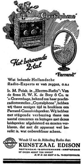
It was recommended
to use a Farrand Senior or Junior
loudspeaker or a Sandar double cone loudspeaker.
The radios were
sold at the
Kunstzaal Edison in The Hague or at a number of agents,
e.g. in Amsterdam,
Rotterdam and Utrecht.
The original price was f 265,-.
The price of a Farrand Senior loudspeaker was f
55,-. The 4A was last sold in 1928; in late
1928 the AC receiver 3W was introduced.
Listen to "Why Don't You Say So"
by the orchestra of Jack Hylton, recorded on January
25, 1926
Back of the 1926 model
Back of the
1927 model
Back of
the 1928 model
In the compartment
under the chassis, a coil set and a battery for negative
grid bias (-4,5V and a tap for -1,5V) can be stored.
Jacks for other voltages, a loudspeaker, earth and
antenna and two rheostats are situated on the back of
the chassis.
Terminals for the LT and HT voltages, the loudspeaker,
earth and antenna and two filament rheostats are located
on the bottom plate of the chassis. They can
be reached via the top cover.The
negative grid voltage is made by a resistor in
combination with a capacitor.
The layout is the same as that of the
1927 receiver.
Top view of the 1926 model
Top view of the 1927 model
Top view
of the
1928 model
Terminals for the LT and HT voltages, the loudspeaker,
earth and antenna and two filament rheostats are located
on the bottom plate of the chassis.
A black painted brass cap (removed here)
covers the tubes.
Under-chassis
view (1926)
Under-chassis view (1927)
Under-chassis
view (1928)
Type 4A with valves on top; early version, 1926
Advertisement in NRC, November 1st, 1926, early version
1927 Model with
internal tubes and internal reaction contro. In the background a Farrand
loudspeaker
The Farrand Senior
loudspeaker
Advertisement for the 1927 version of
the 4A in Radio
Wereld, November 10, 1927


.jpg)
.jpg)
.jpg)

.jpg)
.jpg)
.jpg)
.jpg)
.jpg)
.jpg)
.jpg)
.jpg)
.jpg)

.jpg)

