Click on the picture for the situation before
restauration
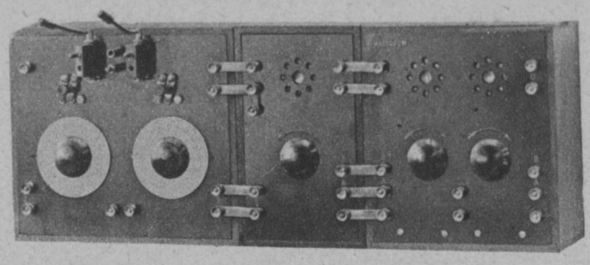
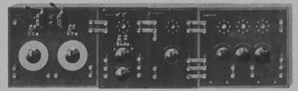
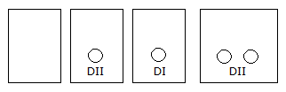
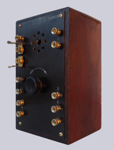
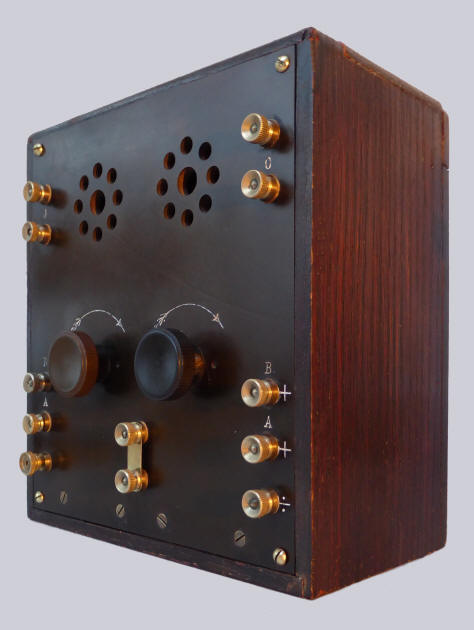
Radioset, blocksystem, consisting of four
interconected units
In brown oak cabinets with ebonite front,
Bakelite knobs and brass coupling strips.
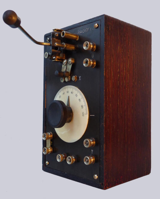
The set consists of a tuning unit
with a fixed and a movable coil, a HF unit with
1 tube and 1 coil, a detector unit with 1 tube and a power
amplifier with 2 tubes, probably all bright emitters.
The remains of 2 Philips DII tubes were found inside the unit, so the probable valve
line-up was Philips DII (HF unit), Philips DI (detector) and 2 x Philips DII
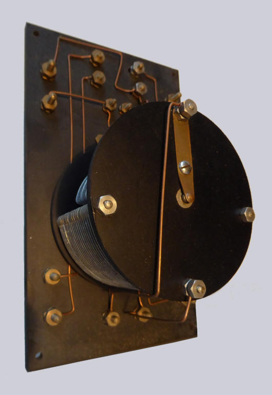
(amplifier). The radio came with a set of original coils. All coils have a solid and a hollow pin. The
coils look British, with a pin diameter of 4.8 mm and a center
distance of 19 mm. One
of the coupling transformers is from the German Böco (almost
certainly not original), and the
other is stamped DPM.There are no other marked
parts.
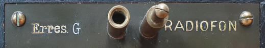
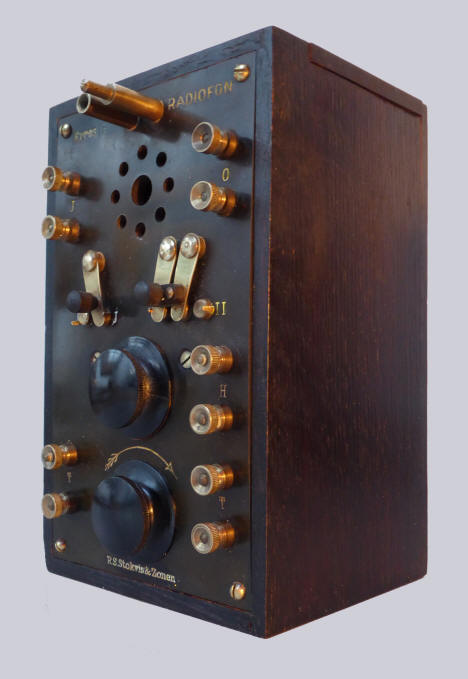
The texts "Erres G RADIOFON" and "R.S. Stokvis &
Zonen" are engraved on the HF unit. The other cabinets have
the text "RADIOFON", with the exception of the last, the
amplifier.
An Erres G, made by Dutch firm N.S.F., was introduced in the Netherlands in 1923, but it
does not look much like this unit.The only similarity is that it
is also an HF module. The link with Dutch trade firm R.S.
Stokvis & Zonen (using the brand name Erres) is still not clear.
History
The radio set comes from Finland, where it was
left in a summer house in 1939 by a Fin who fled to Sweden at
the outbreak of the Winter War between the Soviet Union and
Finland, which began on November 30, 1939 and ended on March 23,
1940.After
WWII, in 1949, the summer house was bought by a Finnish lady who
found the radio there.A grandson
eventually sought information about Erres and Stokvis and ended
up on my website.In 2018 the set was given
to me. It was shipped to the
Netherlands in January 2019. With
many thanks to the generous giver: Carl Fredrik Sandelin,
Helsinki, Finland.
The radio was not made in Finland itself,
because the abbreviations for long and short wave do not match
the abbreviations (L and K) used on the tuning unit.In
Finnish, the letters P (Pitka) and L (Lyhyt) would have been
used.
The radio was probably the first commercial radio imported
in Finland.
The first adverts for the radio appeared in the
Finnish press on October 7, 1923. In the magazine Suomen Kuvalehti
of February 1924, the modular system was first described,
complete with a number of pictures, showing some possible combinations.
1-valve receiver
3-valve receiver (above) and 5-valve receiver
The units were imported by the Finnish company Hedengren
in Helsinki and came from the Danish Radiofon factory in Copenhagen.
The director of Radiofon was E.F. Thestrup-Andersen in 1923; the owner was P. Utzon Buch. Both gentlemen visited a major industrial exhibition in Moscow in September 1923. Radiofon seems to have been a company that was not well known in Denmark itself, because it mainly produced for the foreign market. In the Danish newspaper Fyns Venstreblad, Odense, of November 4, 1924, it is written that "Radiofon, mainly known abroad" has concluded several agreements with the Soviet government in Moscow.
The receiver was also sold in
Norway by Einar Rustad in Kristiania (Olso). In advertisements
from 1923 and in a newspaper article in the same year an
identical set was described.
Listen to "High
Society"
by King Oliver's Jazz Band,
recorded in Chicago, June 24, 1923
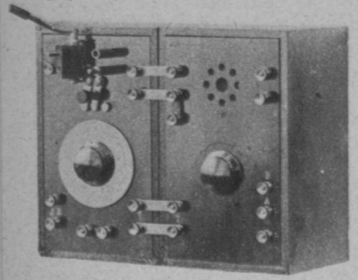
The Radiofon tuner
With a fixed and a
movable coil, an antenna connection, a series / parallel
switch (L/K), a tuning capacitor and a connection for a
frame antenna below.
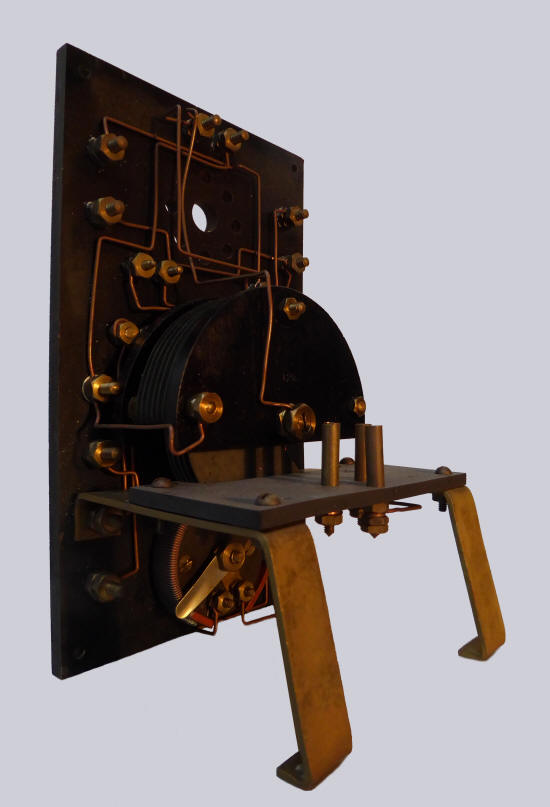
The Erres G / Radiofon HF amplifier
With one tube, a fixed coil,
a switch for switching off the module, a switch for
polarizing the coils on the tuning unit.(in this way,
coils having a different winding direction can also be
used), a tuning capacitor and a rheostat for the
filament current.
The Radiofon detector
With one tube, two
clamps, where a grid leak resistance can be fitted (for
slightly later tubes, not always necessary with bright
emitters) and a rheostat for the filament current.
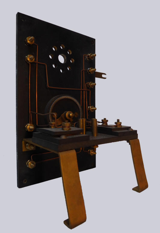
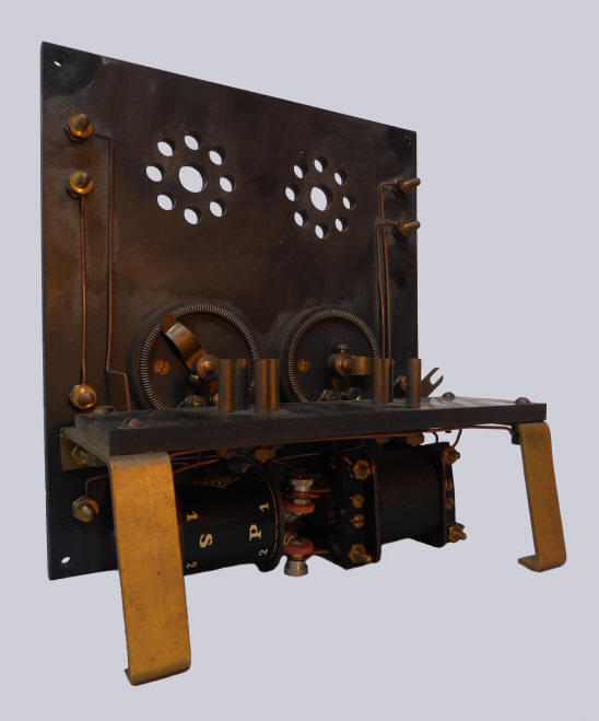
The amplifier
With two tubes and two rheostats for
the flament current. Below, a binding post for a set of
headphones.


.jpg)