Luxuriously
madefour-valve
receiverinmahogany
cabinetwithlockable lid
andebonyfaceplate.
Hinges,lock andlidsupportare gilded.
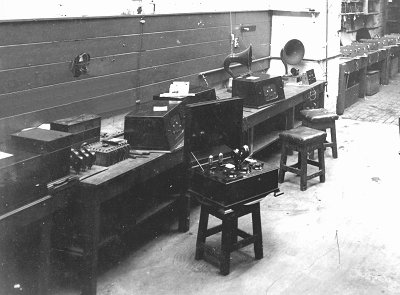
In
this picture, made in the Steward Street
Works in 1926, an F6 receiver can be
seen. The other radios are Symphony
models. In comparison, these radios look
much more modern.
The A.J.S.
catalog of 1925 describes the
unit as follows:
"The A.J.S. 4-valve model has been designed for
those who desire to receive broadcast speech and
music on a loudspeaker, no matter in what part
of the country they are situated. The wavelength
range of the receiver is from 150 metres
upwards, according to the long wave plug-in
coils used. The quality of the reception
obtainable from all A.J.S. receivers is far
above the average. Most critical listeners have
noticed that in radio the low notes are usually
flat and very often are entirely lost. But with
A.J.S. receivers these low notes all come
through with their full value and richness of
tone, and this perfect reproduction extends
right up in the audible scale, and includes
every overtone, nothing is lost. The result is
truly remarkable and is made possible by the
choke method of coupling, which with suitable
valves, such as the A.J.S. Mullard, give equal
volume and considerably purer reproduction than
the average transformer coupling so generally
used."
The receiver can be used with
different types of valves by inserting matching
plug-in filament resistances in the sockets
under each valve.
The radio was made in oak or mahogany.
The earliest model had a slant panel.
The original price of the receiver was £30.10s.0d,
including Mullard valves, batteries, antenna and headphones.
Reicever only: £21.5s.0d.
Listen
to "Dog on the
piano" by the Percival Mackey Dance Orchestra,
recorded November 9, 1925.
The closed cabinet
The top of the receiver with controls
At
the top is a lid that can be removed to give
access to a strip with terminals for the filament
voltage, HT voltages, aerial, earth and loudspeaker.
The connecting wires come out through a slotted hole in
the back of the cabinet. Grid bias voltage can also be connected, and there are
terminals for an optional separating filter.
The valves are located
below the lid, with a plug-in filament
resistor below each valve. Their resistance depends on
the type of valve used (bright emitters, dull emitters,
or "economical" tubes).
The two terminals on the left (with shorting strip)
can be used to connect a frame antenna;
the terminals on the right are for headphones.
In the center is the coil holder with the
two coils. The knobs that are visible above the coils have the following
functions: left: on/off, right: loudspeaker or
headphones.
The three lower knobs (with fine tuning)
are used for primary and secondary tuning; the
right one is used for reaction control.
Under-chassis view
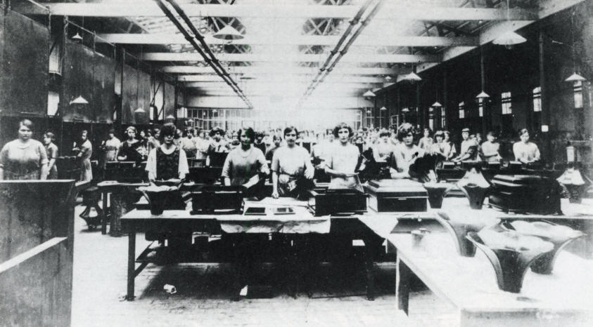
Cabinet and loudspeaker production at AJS in
1925. Almost all the workers are women; a source of cheap labour
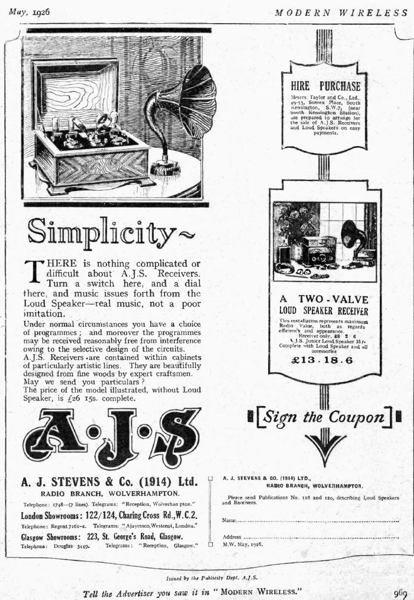
Advertisement in Modern Wireless, May 1926
Ashortuser
manual isfastened in the
middleofthe
front plate
3D picture of the receiver
in the Illustrated London News of 12th December, 1925.
It can be
viewed with 3D-glasses.
Platewithdetails of the
manufacturerand the
valves
Deze pagina is voor het laatst bijgewerkt op
zondag 30 juni 2024


.jpg)
.jpg)
.jpg)
.jpg)
.jpg)
.jpg)