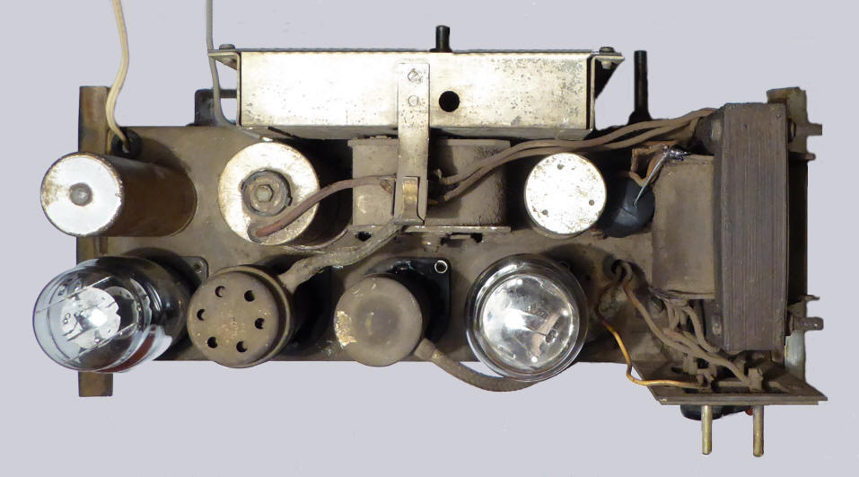
Philips Unknown TRF receiver

 
Simple one-circuit TRF receiver with reaction
In Bakelite cabinet. The knobs from left to right: on/off/ volume control, tuning knob with the wavelength switch behind it, reaction control.
The round celluloid tuning scale is illuminated from above.
On the rear there are antenna and ground connections and a selectivity control knob.
The station scale of the radio has two bands: short wave (15-50 meters) and medium wave (250 to 550 meters). Furthermore, the stations Hilversum I and Hilversum II are shown on the scale.
The radio the has appearance and technical design of the tropical radios Philips 153A and 154A "Lido" made in 1937 and 1938, but the radio is unknown in this version so far.
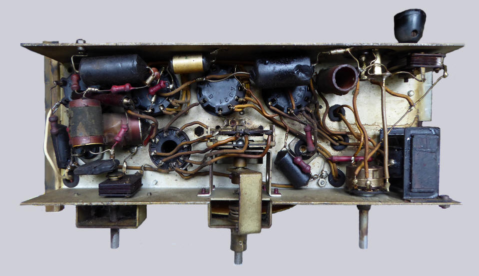
 It could be a residual part of a series of radios originally made for the Dutch East-Indies (presumably a Philips 154A), that because of the outbreak of WWII has not reached the East-Indies and was subsequently 
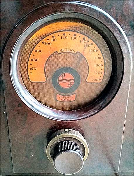
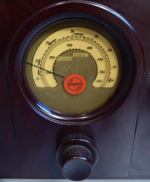
adapted for use in the Netherlands with a medium wave/shortwave coil can and a new station scale. (A type plate has not been placed on the device).
The scale of a Philips 153A. In red (somewhat faded) the indication 20-65 meters; in black 70-200 meters. The Philips logo in black and red and the text "Philips Radio". (picture Prayudi Wibowo). The scale of the radio shown above. In the inner ring the scale 250-550 meters and the names of the stations Hilverum I and Hilversum II. In the outer ring the scale 15-50 meters. Below is the Philips logo in black and red.
Data  
Serial number: no type plate
Dimensions (w × h × d): 32 × 37 × 15 cm
Made in: ± 1940
Purchased in: 2017
Sold in: 2023
Weight: 7.8 kg
Voltages: 110, 125, 145, 200, 220, 245 volt ~
Valves  
Click on a valve for more information

Circuit

Code on the station scale

What was broadcast in 1940?


Listen to "Snoezepoes" by The Ramblers Dance Orchestra, leader Theo Uden Masman, vocals Marcel Thielemans, recorded in "Hof van Holland", Hilversum, March 28, 1940

Back without back panel
The chassis is suspended in rubbers in two slots in the Bakelite cabinet. Two small metal strips keep the chassis in place.
Top view of the chassis
The grid leak resistor is included in the cap of the EF6 detector tube top connector. Ventilation openings are provided to prevent it from getting hot.
Bottom view of the chassis
A number of tear capacitors have a metal envelope.

This page was last edited on 30.09.2023