In robust rectangular,
black canvas covered wooden box with handle and
removable hinged lid.After opening the lid we see an
ebonite panel with two rotary switches, two double
knife switches, two tuning knobs, a clutch control, a
potentiometer control, a small knife switch, a push
button for a buzzer, a Perikon detector with crystal, a
carborundum detector, eight
copper terminals and four wires (two white and two black)
equipped with terminals.
There are two lockable compartments, one in the lid and
one next to the front plate.A
battery can be placed there that provides
pre-tension on the crystals and power for the buzzer.Above that compartment there is a
place to store the headphones.
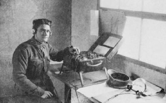
Private (later Lieutenant)
Harry Wilgress Miller, No 2 Wireless Section,
Australian Flying Corps, in the Radio Room with
a Mark III* Short Wave Tuner.He was trained in Australia before
his departure to Europe.(photo:
Australian War Memorial 1917-1918)
The compartment in the lid contains twelve
spare mounted mineral crystals for use in the Perikon
detector.There is a
nickel-plated circular holder in the lid for a pocket
watch and wooden brackets for
holding
maps.
By the middle of the First World War, the
vacuum valve was being successfully developed as a
detector and an amplifier, but its growing use by the
Military did not immediately cause the crystal to become
obsolete. In fact, one of the most well known and widely
used wireless receivers was the Mark III*
Short Wave Tuner.
6595 Tuners were made for an average
price (the price
differed slightly per manufacturer)
of £
30. During the war, the British used
the Mark III* in the trenches. In his
book "Radio! Radio!, Jonathan Hill writes that these
early crystal sets "were used by Royal Air Force
Corps ground stations for the reception of Morse Code signals
transmitted from aeroplanes flying over the battlefields of
the Western Front. The pilots job was to
direct the gunfire of artillery batteries on the ground via
an RFC wireless operator attached to each battery.
With a clear picture of the battlefield on the ground,
the pilots would transmit in Morse the coded position of the
enemy using their Sterling No. 1 spark transmitter
(1915) and the message would be relayed on to the
gunners who would then take the appropriate action. (Jonathan
Hill, Radio! Radio!, page 26). This may seem primitive
according to today's standards, but it was a
technological revolution in its time. It enabled
artillery soldiers to shoot much more accurately than
possible before, without knowing the position of the
enemy and the results of their shelling.
The Sterling No.1 Spark Transmitter
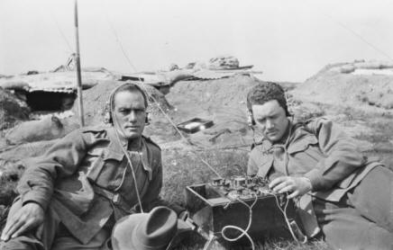
Australian
Marconists listen to a Marconi Mark III* Short
Wave Tuner at a training in Australia (photo:
Australian War Memorial, ± 1916)
Marconi's Wireless
Telegraph Company developed the Mark III* Tuner in 1915. From 1916, the device was also
manufactured by a number of other companies, including
Robert W. Paul, the W/T Factory, A.T.M.Company and Johnson and Phillips.This London-based company made the
Mark III that is part of my collection.
High-quality parts were used in the
manufacture of the set.The
finish was also of very good quality.The housings of most Mark III* tuners
were covered with black painted canvas, but sets
were also made with a mahogany case.In addition, Mark III* Short Wave
Tuners were made with folding aluminum legs (see photo
above), presumably to keep the radio off the ground and
out of the mud.
The Mark III*
Short Wave Tuner is a crystal receiver that uses both
carborundum and Perikon detectors.The wave range is 100-700
meters.
A bright emitter can also be
used instead of the crystal detectors;a switch on the
right side of the set can be used to select the
carborundum detector, the Perikon detector or a radio
lamp.
The Mark III* is tuned
using a buzzer.First the detector switch is set on
the Perikon detector.The inductor
and the variable condenser are set to the estimated
wavelength for receiving a particular station.The switch for the buzzer is then
pressed;this produces
oscillations that work as if a station is transmitting
at the estimated frequency.
Finally, the different tuning knobs are adjusted until
the loudest sound in the headphones is heard;the detectors are then set in the same
way until the most powerful sound is heard, after which
the buzzer can be switched off.The Mark III* Short Wave
Tuner is then ready to receive.
After the war, many Mark III* Tuners
appeared on the surplus market and were bought by radio
amateurs.


.jpg)
.jpg)
.jpg)