Back to the last page

 
First impression

Beautiful cabinet in first varnish with original loudspeaker cloth (a few minor damaged spots), original scale and knobs.

The two back panels are not original but were made in a later period. The colour is a little too light.

The power cord is in a bad state.

The wires to the loudspeakers were extended, convenient when dismantling the radio, but not original.

The output valve 2A5 is leaking and has no emission; the other vales are still very good.

The coupling capacitor has not been replaced.

A resistor is placed over the antenna- and earth buses.

The smooting condensers were replaced by two rather small modern ones (47 uF/450 volts, primary and 22 uF/450 volts, secondary).

The resistance of the secondary winding of the loudspeaker transformer is too high, and at times absent, because of a poor internal connection.

The radio has a nasty hum, the sensitivity is far below standard and the sound is distorted.
Restoration/repair

The power cord was replaced by an exacty matching old cord.

The two back panels we made a little darker.
The receiver was cleaned and dusted.
The switch contacts of the coil drums and the tube sockets were cleaned.

The coupling capacitor (20 uF) was invisibly replaced by a new one (15 uF/1000 volts)

The can containing the smoothing capacitors was opened and the contents were invisibly replaced by a starting capacitor of 12 uF/450 volts as primary and two electrolytic capacitors of 47 uF/450 volts in series (22 uF) as secondary. The saw cut is covered by a mounting bracket and is therefore not visible.

The speaker transformer was opened and the internal wire was fixed firmly to a new nut and bolt. The transformer now measures 1.4 ohms.

The output valve 2A5 was replaced by a new (NOS) one.

The radio crackled and the radio signal was occasionally gone. A bad solder joint in an earth wire proved to be the cause. Soldered.
The resistor over the antenna- and earth bus was removed.
Capacitors C6, C7 and C18 (100 nF) were leaking, replaced invisibly.
Capacitor C20 (500 nF) had no capacity, replaced invisibly.
Capacitors C3 (200 pF) and C5 (300 pF) replaced invisibly.
Tests show that the distortion is located in the radio stage of the receiver.
A capacitor (250 pF, not shown on the diagram) is soldered over pins 9 and 10 of the coil drum. This indicates a repair. The two coupling coils for long wave and medium wave (80 and 20 windings) which are connected to pen 10 of this bus, are interrupted because of lightning. This explains the poor reception. Both coils were repaired
After adjusting the re-wound coils it becomes clear that something in a long wave coil is not completely secured. The short wave coil does not oscillate. On medium wave the reception is still below standard, but the intermediate-frequency coils also have to be aligned. In order to adjust these coils, a special piece of equipment had to be made. The coils are located in a difficult position and a standard tool is completely unsuitable for it. The coils must be adjusted by turning a nut inside the coils, two of them live. 
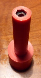
A piece of nylon rod was made into a custom adjusting knob. A heated nut was pushed into the end of the rod and then removed, after first having drilled a small hole at that spot. With this tool adjusting the coils worked effortlessly and immediately yielded the desired result. Reception is fine and the sensitivity is good. At a later stage in the long and short-wave coils will be checked.
 
Two wires in the first coil drum were not properly soldered. After re-soldering, short wave reception is OK; the long wave coil is stil a bit rickety, but can be adjusted.
All the coils have now been adjusted "by ear", but have to be fine tuned using a voltmeter.

Deze pagina is voor het laatst bijgewerkt op vrijdag 13 september 2019