 |
 |
%20klein.jpg) |
|
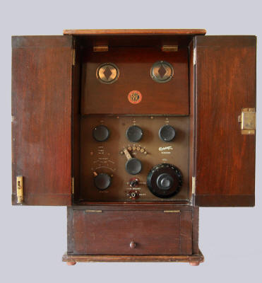
The Chakophone 1B as I bought it |
Picture of a Chakophone 1B
from an auction site |
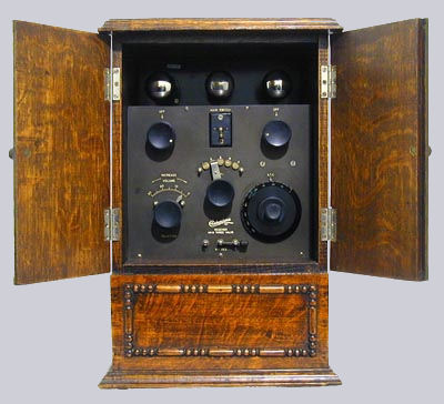
The restored cabinet |
| |
|
THE SITUATION BEFORE
RESTORING |
| |
 |
 |
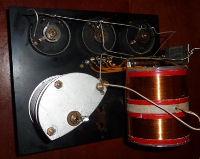 |
|
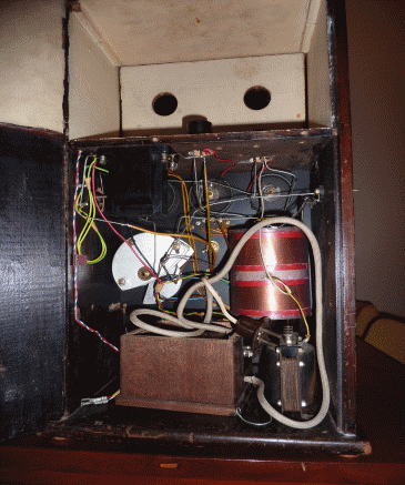
Interior
of the receiver with a battery eliminator |
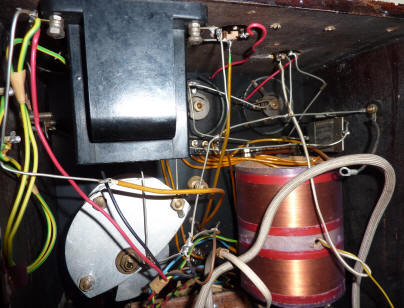
Detail of the chassis |
The chassis removed |
|
| The chassis of the Chakophone 1B was
built in a mahogany cabinet (presumably a real smokers
cabinet) with two doors and a hinged cover below the
chassis. Above the chassis there was a second hinged
flap with a fake BBC logo, fitted with two windows with
brass fittings and red glass. In the white painted
compartment behind the door were the three vertically
placed tubes along with a light bulb. The back showed a
cluttered interior with old and new components and a
modern, poorly constructed power supply. One original
Chakophone coupling transformer was still present, as
well as a Chakophone detector capacitor and a Chakophone
resistor. The coil was rewound with modern wire. |
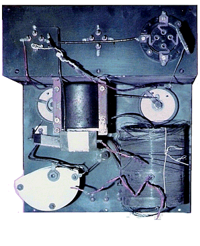
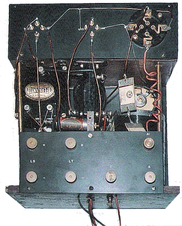
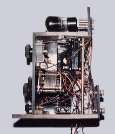
| Information proved difficult to find.
After having approached some contacts in England, I got
some pictures of another Chakophone 1B chassis (see
below). All the information that has been found up to
now related to a newer version of the radio, with an
on/off switch on the location of the middle rheostat and
a change-over switch at the place of the two telephone
jacks. The switch and the connectors for antenna and
earth with my older type
are on the back of the cabinet,
according to a text in an advertisement. Binding posts
and switch are still present . |
|
| |
|
PICTURES OF A RESTORED
CHASSIS |
| |
|
 |
 |
 |
|
|
 |
|
|
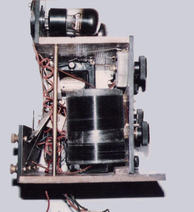
Pictures of another
Chakophone 1B chassis before (first
picture) and after restoration |
|
|
|
 |
|
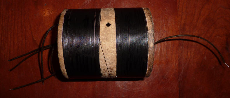
November 8, 2012. Coloured tape was removed from
the coil and the winding was painted black. |
 |
 |
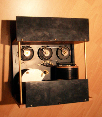 |
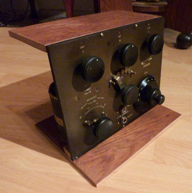
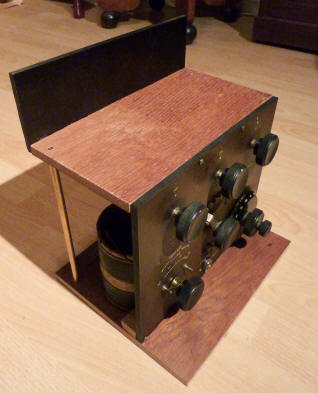
| November 27th, 2012. Old oak
was used to build the chassis |
|
| November 28th, 2012. Brass
supports and the panel for the tubes were added. |
|
November 29th/30th, 2012. Binding post panel and
an original Chakophone resistor were added. The basic form of
the chassis is now ready. |
 |
 |
 |
|
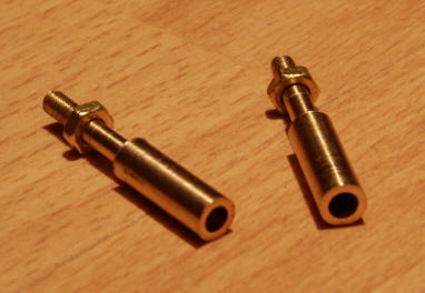
December 1st, 2012. Valve pin holders were made
on my lathe. |
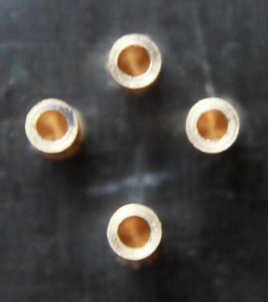
December 2nd, 2012. The first four valve pin
holders. |
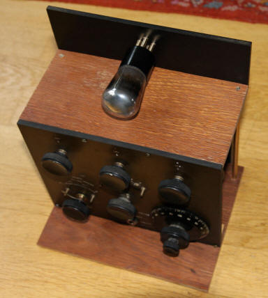
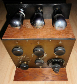
The chassis with the first of the three valves. |
 |
 |
 |
|
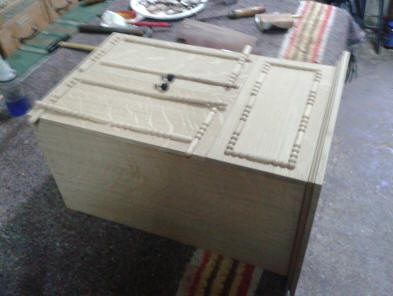
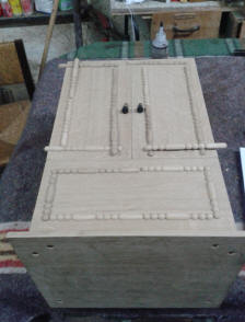
January 2014: the cabinet is ready... |
...including the ornaments |
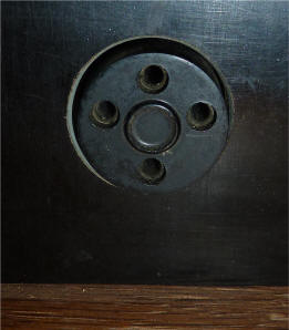
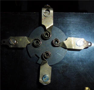
February 9, 2014, the anti-phonetic valve holder
was added |
|
 |
 |
 |
|
The front... |
... and the back of the valve holder |
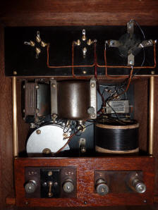
February 19 2014. re-wiring almost complete |