|
|
|
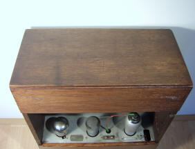
This radio was bought in June 2005. It looked reasonably
well for its age. The oak casing had its normal wear in
some places. The speaker cloth was faded by sunlight,
but it was still original. The front of the radio, made
of aluminium painted black, was in good shape.
As this is an old radio (1930) some
things were missing as well. The back panel consisting
of three oak segments and an aluminium segment for
instance, but this is quite normal for this type of
radio. The 506K rectifier was missing as well. It was
replaced by diode rectifier (without an additional
resistor!) and the rest of the valves (E447, REN904 en
B443) were far from original.
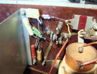
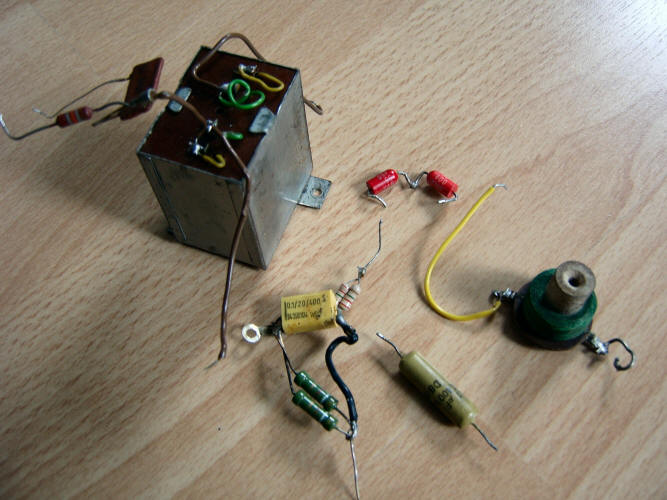
I spotted a choke coil that looked a bit to new, and in
the area below the E447 I noticed some extra decoupling
capacitors and resistors. The LF transformer seemed to
be home made. Volume control was missing and someone had
made a gramophone connexion in the right hand side of
the cabinet.
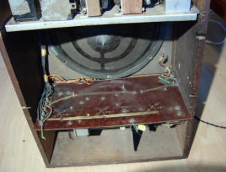
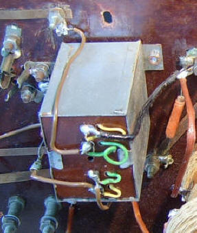
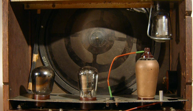
In the picture, the
green choke coil is visible below the wire that runs to
the top of the E447. Next to this coil, also below the
E447, a yellow mepolesco condenser can be seen. The 506K
rectifier has to be mounted upside-down in the right
hand corner above the E447. Volume control was not in
its place to the right of the E447. The home made LF transformer
is visible below the B443 and the REN 904. |
|
.JPG)
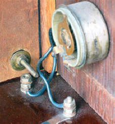
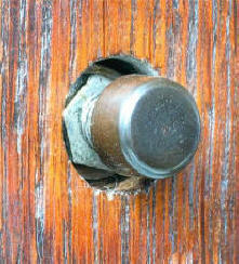
The slotted grooves in the side of the
cabinet are original and were made to accommodate the cables for power,
antenna and earth (right) and an extra loudspeaker
(left). |
|
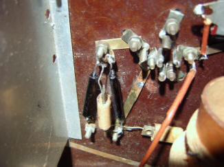
| Chassis plate and rectifier |
|
The brass strips have
been partially restored. On the right a green resistor.
Volume control is missing there. Just visible below the pertinax plate, a yellow mepolesco condenser. |
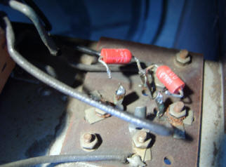
A nice detail in this radio is the
brass strip wiring. It looks a bit like modern
i.c. Alas, some of them
were missing on top of the pertinax plate. To solve this
problem the missing connections had been made underneath
the chassis with nasty blue wire! In spite of all this,
the radio was working reasonably well, although it was
playing very loud, mainly because of the wrong valves and the
missing volume control.
I started by making
new strips. I found some thin brass plate and
discovered that was very easy to cut. When all the
strips were screwed back and connections were made, I
could remove the blue connecting wire underneath.
|
|
 |
|
The partially removed
diode rectifiers. |
|
I managed to
buy a 506K rectifier at the NVHR meeting in
Doorn.
Not a new one, but
still good
enough for this radio.
A support bracket for this valve was made. The
diodes could be removed. Now I had to look for
the rest of the valves, the Philips 4000 LF
transformer and a 1K5 volume control. |
|
| In a spot
were a 50 Ohm resistor had to be, the
choke coil mentioned before was mounted. A nice
way of improving selectivity a bit, but not
original. It had to go! |
 |
|
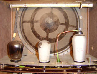
The "wrong" valves
from left to right:
B443, REN904, E447. On the upper right the 506K rectifier
has to be mounted upside-down. The Philips 2044 loudspeaker
was not secured in some places. That was an easy one!
|
|
|
| The next step was
removing the unnecessary decoupling components in the E447 area and
making a new brass strip. I still have to look for more
original resistors. |
|
|
|
|
Because I had to wait for the valves and
the Philips 4000 LF transformer, I could focus my attention
to the back panel. In the city where I live, Utrecht, I
found a small do-it-yourself store where someone was
willing to make the three segments to measure. Ammonia
was used to age the wood a little bit; after that a
little pickle took care of the correct colour.
|
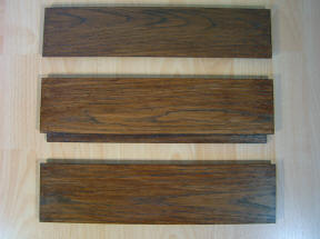
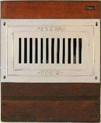
The ready-made panels.
There is almost no
difference in colour between the oak panels and the
original oak casing. The gramophone connection is
visible between the E424 and the E452T. |
|
|
Low frequency transformer |
|
 |
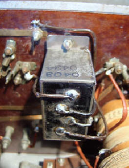 |
| Old
situation with home-made LF transformer. |
The "new" Philips LF transformer. |
| When finally the
valves, a temporary volume control and the Philips 4000
LF transformer arrived, the next step in restoring the
radio could be made. The home-made LF transformer was
removed and the Philips 4000 transformer was put in its
place. |
|
|
|
 |
|
The new valves and the
support bracket for the 506 rectifier.
The original valve set was used: apart from the
506K, the B443 as amplifier, the E415 as detector and
the E442 as HF valve. This picture still shows the C443, the E424 and the E452T. |
|
|
I thought that
this was the end of the restoration project, but this
proved not to be true. The old paper condensers were in
a bad state and had to be replaced by new ones. Alas, an
original circuit for this radio was not available in
readable form so I had to use a clear, but in the end
not completely correct circuit that was available on
John Hupse's website to replace the old paper condensers
by new ones, but unfortunately this resulted in a nasty
100Hz hum. Many emails and consults by Ed Plevier and
John Hupse followed, and in the end the problem was
found: a fault in the circuit.
 |
 |
The correct
circuit is now available on my website. Amazing how a radio, made in 1930, can keep three people busy for a
number of days. |
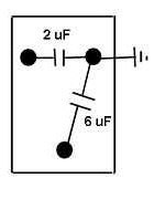
| The new
condensors were connected like this... |
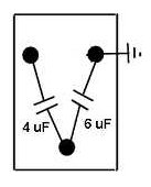
...and had to be connected like this |
|
|
|
Many thanks to
John Hupse, Philip Apeldoorn, John Hupse, Ed Plevier
and Arjan van Schaik for
their advise, pictures and components. |