|
|
|
 |
| |
|
d.jpg) |
| Frame antenna
with built-in amplifier |
|
In wooden housing with pertinax front and
wooden base.
On the outside of the housing is an
antenna winding with two loops. |
 |
|
Above right is an on/off switch, on the left a
light that lights up when the amplifier is on. Bottom
left is a wavelength switch for long, medium and short wave (GO,
MO and OC).
The tuning knob is at the right. |
|
Because the antenna mainly receives the
magnetic component of the antenna signal, a large part
of the interference is blocked.
The built-in amplifier amplifies the antenna signal, so
that good reception is also possible indoors. |
|
This type of antenna was especially
popular in Belgium and France. |
|
R.R Radio
S.A.
is founded in Brussels in March 1930 by Messrs Roger Roy
and Marc Revol.
The
address is 10, Impasse de l'Hopital.
In 1934 the company moved to a new factory in
Anderlecht, 44-46, Rue des Goujons.
In 1953 the company moved again, to the Chaussée de
Ninove 291. The company makes beautifully designed
radios until the beginning of the 1950s of the last
century.
RR Radio stopped around 1966. |
| An example of a few radios
made by R.R. Radio
here. |
|
| Serial number |
|
| Made in |
± 1950 |
| Purchased in
|
2018 |
| Dimensions (h x w x d) |
29,3 x 21 x 8 cm |
| Voltage |
220 volts |
|
 |
Click on a valve for more
information |
 |
Click on the circuit to
enlarge |
|
|
.jpg) |
|
Back |
|
After the loop antenna is connected to the mains,
the two plugs on the rear are connected to the antenna and
groundbus of a radio unit and a radio station is found on the
radio, the antenna can be tuned by means of the right button.
By turning the antenna the
reception can be further optimized. |
d.jpg) |
|
Inside |
|
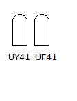
Between the on/off switch and the pilot light
there are two wire-wound resistors that provide the operating
voltages of the amplifier.
At the bottom left, the tuning capacitor with next
to it the wavelength switch and below the long and medium wave
coils. The shortwave
coil is situated above the wavelength switch. |
|
|
|