Type R.B.I.B Long Range Model
M.19, made by Marconi's Wireless Telegraph Co, Ltd.
(the chassis of the early models was made by Plessey, Holloway, London). The
radio is housed in a polished mahogany cabinet bearing
the BBC stamp and GPO Registration No. 0175, and a
Marconi-logo on the lid.
On the
right hand side of the cabinet there are a number of
binding posts for two sets of headphones (or a
loudspeaker) and the binding
posts for filament and anode voltages. On the left
connecting leads for antenna and earth. A reaction
control unit with a lever can be seen on the right.
Originally this circuit used "R" type bright emitter
valves which were susceptible to failure due to the very
high temperature of the filament. A rheostat was
provided to control the filament current and thereby
prolong the life of these expensive valves. Later sets -
like this one - retained this rheostat when "D.E.R."
(Dull Emitter Receiver) valves were introduced. The
rheostat is operated by a control rod protruding from
the left hand side of the cabinet. When the rod is
pushed right in, the filament circuit is disconnected
from the accumulator.
The price of the
radio was £24, including £1
15s for BBC royalties and 12s 6d royalty per valve to Marconi.
Better loudspeaker reception was possible by using an
additional two-stage amplifier, the A2, brought out in
1924, or the earlier NB2 with bright emitters.
Tuning
A
number of plug-in tuning range blocks were available to cover wavelengths
from 300 to 2900 metres. Each block contains two
"pancake" coils which provide aerial (antenna) and RF
amplifier anode-tuning respectively. A pair of rods with tuning
knobs project through the side walls of the
cabinet, one to the left and one to the right. To the
inner end of each rod is attached a copper plate or
spade. As the rods are slid in and out of the cabinet
the copper plates are caused to slide across their
respective pancake coils and thereby influence the
tuning. The following list from a contemporary
publication gives an insight into what one could receive
using the blocks originally provided with the set:
300-390
m
British broadcasting
390-530
m
British broadcasting
550-700
m
shipping
700-900
m
aircraft
2500-2900 m
Paris
This set still has two
tuning range blocks: 390-530 m and 1300-1700 m.
Operation
The aerial
(antenna) is connected, depending upon its length, to
the appropriate "Aerial" terminal, 1, 2 or 3. Aerials
have a certain natural capacitance to ground and the
longer the aerial the greater the capacitance. This
capacitance appears across the aerial tuning circuit,
thereby affecting its resonant frequency. Now the aerial
tuning circuit needs to cover much the same wavelength
range for aerials of substantially different lengths
(and therefore different capacitances). Medium length
aerials (of approximately 15 m) are connected to terminal
2 and thence via a coupling capacitor to the aerial
tuner. Aerials much longer than this (up to
approximately 30 m) are connected to terminal 1 where a
smaller value of coupling capacitor is used which
reduces the capacitive loading on the tuned circuit to
roughly that of a 15 m aerial. Short aerials are
connected to terminal 3 where the act of inserting the
aerial plug causes a capacitor to be connected between
the aerial and earth, raising the overall aerial
capacitance up to roughly that of a 15 m aerial. In this
way the aerial tuning circuit is always loaded by
roughly the same aerial capacitance. Hence the range of
wavelengths covered remains substantially constant for
different lengths of aerial.
The first valve
amplifies the RF signal from the aerial tuner and the
output from its anode is tuned and fed to the second
valve which is wired as a grid-leak detector. The
grid-leak resistor is marked 2Ω
which is the archaic way of writing 2MΩ.
The output from the detector anode contains the
recovered audio signal and a certain amount of the
carrier wave RF as well. This RF output is series tuned
by the regenerative unit and fed back to the detector
input with the correct phase needed to achieve positive
feedback. The setting of the lever on the regenerative
unit influences the strength of feedback and hence the
selectivity of the circuit.
The audio output
from the detector is connected to the (low impedance)
primary of an LF feedback transformer. The audio output
from the (high impedance) secondary of this LF feedback
transformer is connected to the grid of the first valve
via an RF choke. The first valve then amplifies this
audio signal before coupling it to the headphones via
another RF choke.
Listen to "You'll
Hear Me Calling Yoo Hoo" by the orchestra of
Jack Derrick,
recorded February 3rd, 1923
Front view
The set has a pair
of detachable panels at the front. The top panel
features two viewing portholes which were used to keep
an eye on the filaments of the Osram D.E.R. valves. The
bottom panel is held with two screws and covers a void
where the HT battery could be housed.
The sockets for antenna and earth.
The
sockets for phones, and filament and anode voltages.
"Dull" emitters still produce
a reasonable amount of light in the evening...
Advertisement for the Marconiphone V2
Advertisement in Modern Wireless, August 1923
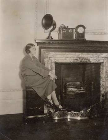
Two pictures of a Marconiphone V2 with Sterling
loudspeaker in a contemporary living room

.jpg)

.jpg)


.jpg)